TE Connectivity – Leading the Way in Global Industrial Technology
81This article provides a comprehensive introduction to TE Connectivity, a global industrial technology company. It covers aspects such as company ov...
查看全文全站搜索
How to know the Value of Inductance of an Inductor using Standard & Color Codes – Calculators & Examples
For small Inductors like air-core, iron-core, ferrite-core or SMD inductors etc., the surface area of the component is very small hence it is not possible to print the exact value of inductance and other parameters (nameplate rating) on it. This way, some special notations and marking are used e.g. color bands, color dots, digits, numbers and alphanumeric characters which known as inductor color codes and they are used to indicates the different characteristics and values of inductance of inductors. Generally, the values of these indictors are in μH (Microhenries 1 x 10⁻⁶).
Related Posts:
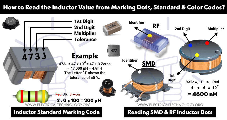
Let see how to read the value of inductors by using the standard marking codes?
If an inductor has two numerical values, or any two digits and a letter like 11N, it means the value is 11 nH (nanohenry).
For example: 6R8 = 6.8 μH.
For examples:
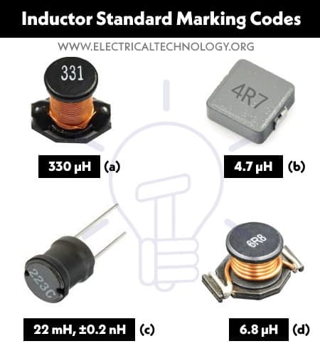
Most of the inductors have three numerical values printed on it. For example, 220, 221, 222, 223, 331, 332 etc. Let’s see how to read these values. Suppose the printed value on an inductor is “332”
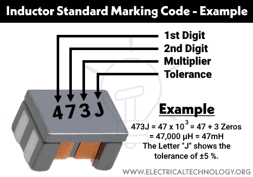
Similarly, if the specials marking code on the inductor is 223J: (3 Digits + 1 Alphabet), the fourth one character (“J” in this case) shows the tolerance of the inductor: For example:
Tolerance of Inductors
There are Capital letters printed on the inductors except the value of inductance such as 223J.
The following table shows the tolerance for inductors indicated by Letters.
| Letters | Tolerance in % |
| B | ±0.15 nH |
| C | ±0.2 nH |
| S | ±0.3 nH |
| D | ±0.5 nH |
| F | ±1% |
| G | ±2% |
| H | ±3% |
| J | ±5 % |
| K | ±10% |
| L | ±15% |
| M | ±20% |
| V | ±25% |
| N | ±30% |
The following symbols and units are used to represent the values of inductance of indictor in Millihenries (mH), Microhenries (μH) & Nanohenries (nH).
| Symbol | Abbreviation | Value in Numbers |
| mH | Milli-henry | 10-3 |
| μH | Micro-henry | 10-6 |
| nH | Nino-henry | 10-9 |
Related Posts
Apart from the text marking on inductors, there are special inductor color codes namely “EIA” (Electronic Industries Association) and “Mil-Spec” (Military Specification). There are three, four or five color bands printed on the inductor which shows the inductance of the inductor and tolerance. Let’s see how to read 2, 3 and 4 bands color codes inductor as follows:
If there are three color bands marked on an inductor, it means
The Three color bands inductor as Red, Brown & Gold:
Red = 2, Brown = 1 & Gold = 0.1 i.e.
Mostly, the three color band inductors have a tolerance of ±20%. This way, the value of the inductor is 2.1 µH – ±20%.
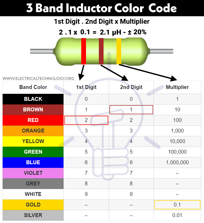
The following table shows the three bands inductor color codes and its values.
| Band Color | 1st Digit | 2nd Digit | Multiplier |
| BLACK | 0 | 0 | 1 |
| BROWN | 1 | 1 | 10 |
| RED | 2 | 2 | 100 |
| ORANGE | 3 | 3 | 1,000 |
| YELLOW | 4 | 4 | 10,000 |
| GREEN | 5 | 5 | 100,000 |
| BLUE | 6 | 6 | 1,000,000 |
| VIOLET | 7 | 7 | – |
| GREY | 8 | 8 | – |
| WHITE | 9 | 9 | – |
| GOLD | – | – | 0.1 |
| SILVER | – | – | 0.01 |
| First Digit | Second Digit | Multiplier | |
| 0 Black1 Brown2 Red3 Orange4 Yellow5 Green6 Blue7 Violet8 Gray9 White | 0 Black1 Brown2 Red3 Orange4 Yellow5 Green6 Blue7 Violet8 Gray9 White | x1 Blackx10 Brownx100 Redx1000 Orangex10000 Yellowx100000 Greenx1000000 Bluex10M Violetx100M Grayx1G Whitex0.1 Goldx0.01 Silver | |
| Inductance: | |||
If there are four color bands printed on an inductor, it means
The Four color bands inductor as Green, Blue, Brown & Gold:
Green = 5, Blue = 6, Brown = 100 & Gold = ±5% i.e.
The fourth band as Golden color shows the tolerance of ±5%. Therefore, the value of the inductor is 56 mH – ±5%.
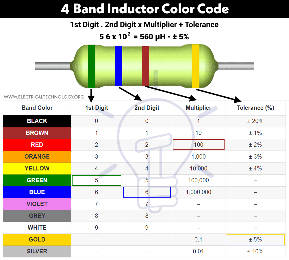
The following table shows the four bands inductor color codes and its values.
| Band Color | 1st Digit | 2nd Digit | Multiplier | Tolerance (%) |
| BLACK | 0 | 0 | 1 | ± 20% |
| BROWN | 1 | 1 | 10 | ± 1% |
| RED | 2 | 2 | 100 | ± 2% |
| ORANGE | 3 | 3 | 1,000 | ± 3% |
| YELLOW | 4 | 4 | 10,000 | ± 4% |
| GREEN | 5 | 5 | 100,000 | – |
| BLUE | 6 | 6 | 1,000,000 | – |
| VIOLET | 7 | 7 | – | – |
| GREY | 8 | 8 | – | – |
| WHITE | 9 | 9 | – | – |
| GOLD | – | – | 0.1 | ± 5% |
| SILVER | – | – | 0.01 | ± 10% |
| First Digit | Second Digit | Multiplier | Tolerance |
| 0 Black1 Brown2 Red3 Orange4 Yellow5 Green6 Blue7 Violet8 Gray9 White | 0 Black1 Brown2 Red3 Orange4 Yellow5 Green6 Blue7 Violet8 Gray9 White | x1 Blackx10 Brownx100 Redx1000 Orangex10000 Yellowx100000 Greenx1000000 Bluex10M Violetx100M Grayx1G Whitex0.1 Goldx0.01 Silver | ± 1% Brown± 2% Red± 3% Orange± 4% Yellow± 0.5% Green± 0.25% Blue± 0.10% Violet± 0.05% Gray± 5% Gold± 10% Silver |
| Inductance: | |||
| Tolerance: | |||
Related Posts:
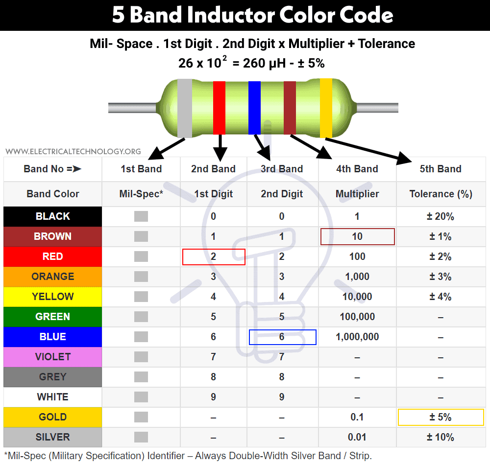
If there are five color bands printed on an cylindrical molded inductor, it means
The Five color bands inductor as Silver , Red, Blue, Brown & Gold:
Silver = Mil-Spec, Red = 2, Blue = 6, Brown = 10, & Gold = ±5% i.e.
The fifth band as Golden color shows the tolerance of ±5%. Therefore, the value of the inductor is 260 µH – ±5%.
The following table shows the four bands inductor color codes and its values.
| Band No =➤ | 1st Band | 2nd Band | 3rd Band | 4th Band | 5th Band |
| Band Color | Mil-Spec*1 | 1st Digit | 2nd Digit | Multiplier | Tolerance (%) |
| BLACK | 0 | 0 | 1 | ± 20% | |
| BROWN | 1 | 1 | 10 | ± 1% | |
| RED | 2 | 2 | 100 | ± 2% | |
| ORANGE | 3 | 3 | 1,000 | ± 3% | |
| YELLOW | 4 | 4 | 10,000 | ± 4% | |
| GREEN | 5 | 5 | 100,000 | – | |
| BLUE | 6 | 6 | 1,000,000 | – | |
| VIOLET | 7 | 7 | – | – | |
| GREY | 8 | 8 | – | – | |
| WHITE | 9 | 9 | – | – | |
| GOLD | . *2 | . *2 | 0.1 | ± 5% | |
| SILVER | – | – | 0.01 | ± 10% |
| MIL Spec | First Digit | Second Digit | Multiplier | Tolerance |
| 1 Silver | 0 Black1 Brown2 Red3 Orange4 Yellow5 Green6 Blue7 Violet8 Gray9 White | 0 Black1 Brown2 Red3 Orange4 Yellow5 Green6 Blue7 Violet8 Gray9 White | x1 Blackx10 Brownx100 Redx1000 Orangex10000 Yellowx100000 Greenx1000000 Bluex10M Violetx100M Grayx1G Whitex0.1 Goldx0.01 Silver | ± 1% Brown± 2% Red± 3% Orange± 4% Yellow± 0.5% Green± 0.25% Blue± 0.10% Violet± 0.05% Gray± 5% Gold± 10% Silver |
| Inductance: | ||||
| Tolerance: | ||||
Related Posts:
The following calculator will convert the value of inductance printed in code on an inductor to the four bands of inductor color codes. This calculator supports 4-colored strips and values of inductances in H (Henries), mH (milli-henries) and µH (micro-henries). Just put the code of the inductor in digits e.g. 100, 102, 233 etc and click on calculate for the desired color codes.
| Enter Values | |||
| Enter Inductor Code: | H – (Henrys)mH – (MilliHenrys)µH – (Microhenrys) | ||
| Tolerance %: | 5% 10% 20% | ||
| The Color Code is: | |||
  | |||
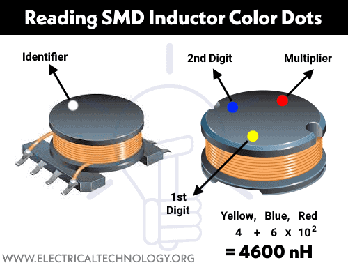
On SMD inductors, there is no possibility to print the inducting marking or color code bands due to the small surface area of the tiny component. This way, only colored dots are printed on these inductors to represent the value of inductance in nanohenries. Keep in mind that these dots do not represent the polarity of the inductors and can only be used in clockwise direction to determine the value of SMD inductors.
For Example:
The colored dots in clockwise direction on an SMD inductor are Yellow, Blue & Red. This way:
Hence the value of the SMD inductor is 4600 nH.
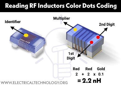
Radio frequency or RF inductors are the same like SMD and chip inductors in size. The marking method is the same as the above one i.e. if there is only one color dot, it shows the inductance and other specifications can be seen in the related datasheet.
On the other hand, if there are three colored dots printed on the RF inductors, the first two opposite colored dots (in clockwise direction) show the first and second digit (significant figures) respectively while the single dot on the other end represents the multiplier.
Good to know: The single or three dots are not supposed to represent the polarity of the inductor but only the value of inductance in nanohenries (nH).
For Example:
The colored dots in clockwise direction on an RF inductor are RED, RED & Gold. This way:
Hence the value of the RF inductor is 2.2 nH.
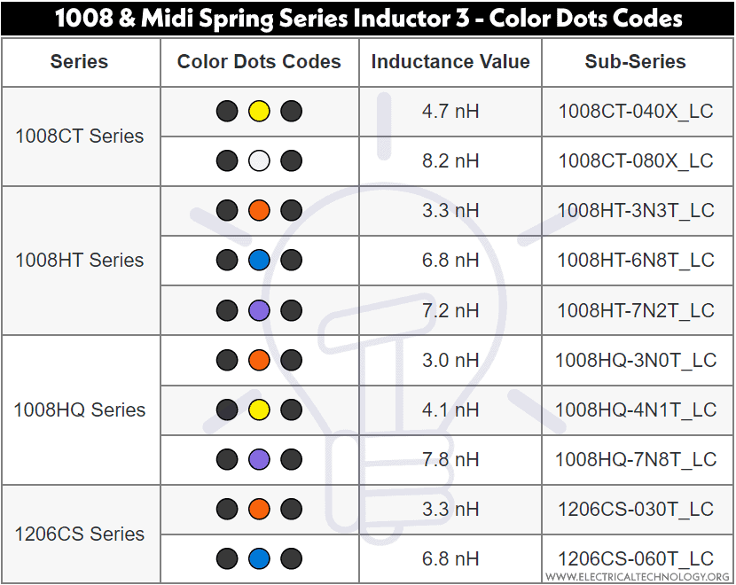
The following table shows the 1008 and Midi Spring Series Inductor 3 – Color Dots Codes and its values of inductances in nH.
| Series | Color Dots Codes | Inductance Value | Sub-Series |
| 1008CT Series | ⚫ 🟡 ⚫ | 4.7 nH | 1008CT-040X_LC |
| ⚫ ⚪ ⚫ | 8.2 nH | 1008CT-080X_LC | |
| 1008HT Series | ⚫ 🔴 ⚫ | 3.3 nH | 1008HT-3N3T_LC |
| ⚫ 🔵 ⚫ | 6.8 nH | 1008HT-6N8T_LC | |
| ⚫ 🟣 ⚫ | 7.2 nH | 1008HT-7N2T_LC | |
| 1008HQ Series | ⚫ 🔴 ⚫ | 3.0 nH | 1008HQ-3N0T_LC |
| ⚫ 🟡 ⚫ | 4.1 nH | 1008HQ-4N1T_LC | |
| ⚫ 🟣 ⚫ | 7.8 nH | 1008HQ-7N8T_LC | |
| 1206CS Series | ⚫ 🔴 ⚫ | 3.3 nH | 1206CS-030T_LC |
| ⚫ 🔵 ⚫ | 6.8 nH | 1206CS-060T_LC |
Related Posts:
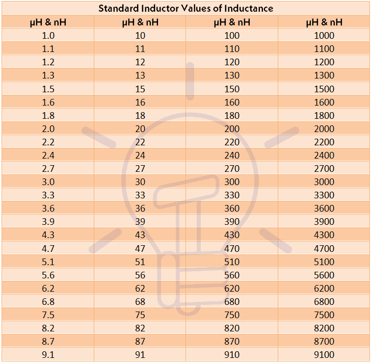
Following is the table of most common used and available inductors both in µH (microhenries) and nH (nanohenries).
| Standard Inductor Values of Inductance | |||
| µH & nH | µH & nH | µH & nH | µH & nH |
| 1.0 | 10 | 100 | 1000 |
| 1.1 | 11 | 110 | 1100 |
| 1.2 | 12 | 120 | 1200 |
| 1.3 | 13 | 130 | 1300 |
| 1.5 | 15 | 150 | 1500 |
| 1.6 | 16 | 160 | 1600 |
| 1.8 | 18 | 180 | 1800 |
| 2.0 | 20 | 200 | 2000 |
| 2.2 | 22 | 220 | 2200 |
| 2.4 | 24 | 240 | 2400 |
| 2.7 | 27 | 270 | 2700 |
| 3.0 | 30 | 300 | 3000 |
| 3.3 | 33 | 330 | 3300 |
| 3.6 | 36 | 360 | 3600 |
| 3.9 | 39 | 390 | 3900 |
| 4.3 | 43 | 430 | 4300 |
| 4.7 | 47 | 470 | 4700 |
| 5.1 | 51 | 510 | 5100 |
| 5.6 | 56 | 560 | 5600 |
| 6.2 | 62 | 620 | 6200 |
| 6.8 | 68 | 680 | 6800 |
| 7.5 | 75 | 750 | 7500 |
| 8.2 | 82 | 820 | 8200 |
| 8.7 | 87 | 870 | 8700 |
| 9.1 | 91 | 910 | 9100 |
Charts & Tables in image format:


This article provides a comprehensive introduction to TE Connectivity, a global industrial technology company. It covers aspects such as company ov...
查看全文
Two years after the CHIPS Act, the U.S. semiconductor industry is seeing significant growth, with domestic manufacturing capacity expected to tripl...
查看全文
Nexperia is a global leader in the semiconductor industry, specializing in discrete semiconductors, logic devices, and MOSFETs. Headquartered in th...
查看全文
On May 8, 2024, the Semiconductor Industry Association (SIA) in partnership with the Boston Consulting Group (BCG) released a report on the global ...
查看全文 0
0High Quality IC Suppliers

您好!请登录